
The Survey
By scrutiny of the road maps in the DDX194 collection at the Lancashire County Record Office it would appear that the surveyor worked in daily stages. His measuring wheel, called a dimensurator, was set at zero each day. Each of these twenty-five surveys has been given a Route Number for easy reference in Chapter 3. The evidence suggests that he started at Warrington and finished the stage at Wigan after 12½ miles with an overnight stop. Setting his wheel reading to zero he then walked to Preston. The next stage went to Lancaster followed by a walk over the sands of Morecambe Bay to Cartmel. Whilst in that part of Lancashire, now Cumbria, a series of measurements were taken the sequence of which is not certain, but a likely route has been assumed and shown in Routes Nos. 7 to 17 inclusive in Chapter 3. After his return to Lancaster he came back to Poulton le Fylde via a coastal route through Pilling Sands. The next stage of 17 miles took him to Preston.
What appears to be a second circuit of the area, bearing in mind the year 1685, was from Preston to Inglewhite. From there he went to Garstang via Beacon Fell. The next stage to Lancaster went by Forton and Galgate and whilst in Lancaster he made a measured visit from Clougha Beacon five miles away passing the tyburn [gallows, now known as Golgatha] half a mile out of town.
Three distinct and detailed surveys were made to a large scale of Preston, Lancaster and Wrightington Hall. The plan of Lancaster has already been the subject of a paper. The details of Preston town with a schedule of its inhabitants and the plan of Wrightington Hall are shown in subsequent sections.
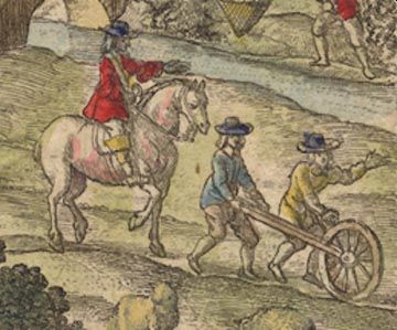
It is likely that the team consisted of three men and three horses. Two of whom would be surveyors alternating at regular intervals between walking with the wheel and scribing whilst on horseback. Using this method they could cover long distances each day. The third man would be responsible for carrying luggage, instruments and provisions. He would carry out general duties besides acting as chainman when required. He may even have done a stint on the wheel pushing. Additional casual help would be called upon to supply local knowledge of names, places and directions. Their attire would consist of a wide brimmed felt hat, thigh length coat buttoning to the neck, breeches buckled at the knee, stockings and stout boots. Their raincoats would be made from oiled cotton.
The documents in the collection pose some interesting observations. The paper on which the drawings were made is good quality, hand made, which can be dated from the watermarks. The double lines representing the roads wander over the sheets with no apparent direction, some times disjointed, presumably to save paper. All the bends in the roads are clearly marked which were ahead of the surveyor as he rode along. Even so the distances are neatly written, in ink, in relatively small figures. Whist these were field notes taken for preparation of a finished product in the style of the Ogilby road maps, with which Gregory King was quite familiar, they are not consistent with a scribe on the move. There are no marks on the papers, which would be caused by different weather conditions. It is the considered opinion of the Lancashire County archivist Mr Bruce Jackson that these existing documents are a second draft which would account for the neatness of the writing probably written in dry conditions on a table. The reference numbers allocated to the individual sheets by the Lancashire Record Office do not indicate the route and direction of the surveyor and a cross-reference is suggested in Appendix No 1.
Surveying Instruments Used
A dimensurator, a name used by Ogilby in 1675, was used for measuring linear distances mainly on roads but occasionally on tracks/paths. This consisted of a wooden wheel, fitted with an iron tyre 99 inches long, which when wrapped round the wheel had a diameter of approximately 31½ inches. For every two revolutions of the wheel a distance of 198 inches or one pole was travelled. The axle of the wheel was connected via bevel gears and rods to three concentric dials contained in the handle, which indicated the distance travelled. The dials were graduated in poles, furlongs and miles of statute measure of 5½ yards to one pole, 40 poles to one furlong and 8 furlongs to one mile. The outer dial had 40 segments marked round the edge each representing one pole. One complete revolution of the hand indicated 40 poles on the outer dial and one furlong on the middle dial. After eight revolutions the hand indicated 40 poles on the outer dial, 8 furlongs on the middle dial and 1 mile on the inner dial. During this distance the wheel would have made 80 revolutions.
The distances marked on the maps are remarkably accurate considering the state of the road and track surfaces over which the wheel was pushed. For example the readings appear as 11 : 6 : 19 meaning 11 miles 6 furlongs and 19 poles at Clifton village on route from Poulton to Preston.
For accurate surveying of a town like Preston the linear distances were taken with a surveyor’s chain. Each chain was 22 yards long and made up of 100 links each 7.92 inches long. Identical chains are still used today more than 300 years later. This size of chain with 100 links was very convenient for drawing maps such as Preston to a scale of 1 inch to 200 links, that is, 1:1584. For measuring angles a simple theodolite was used, which consisted of a telescope mounted over a large protractor and compass all set level upon a tripod. Each degree could easily be subdivided into 60 minutes using a Vernier scale.
The Method Used
When surveying a street like Church Street which was curved along its length the chain was first laid out in a straight line a distance of about 600 yards on the whole length of Fishergate. It was then extended along Church Street as far as possible until it reached the side of the road at a bend near the church. The lateral distances from the chain to the buildings on each side (offsets) were then measured at various intervals along its length. The chain was then moved along on a different but continuous line to the next bend and measured. The side measurements were recorded again. The angle contained between the line of the first and second chain was 161 degrees 43 minutes and between the second and third line was 169 degrees 50 minutes. When the chain was laid along Cheapside towards Friargate the angle measured from the Church Street/Fishergate line was 95 degrees. This chain junction was used as a zero datum for all measurements. From this long base line all the distances, to the nearest link, and angles to the fraction of a degree, were measured, so enabling an accurate plan of the streets to be drawn. The plan, prepared from these measurements, showed the building line complete with all the nooks and crannies.
Whilst measuring the streets the surveyor, Gregory King, took dimensions of some buildings, also in links, such as the guildhall, town hall, church, school, alms houses in Fishergate and Church Street, Correction House, and the Friary. He also located the water wells in Fishergate, Mince Pitt wind (also known as Dundee Lane) and Lady Well by the Friary.[Wind/weind means narrow entry] This information is shown on documents DDX194/1 /3 /4 /8 /9 /10.
The next phase was to draw the streets freehand, and this time mark the size of the frontage and the name of the occupant of every house (with number of stories), inn, shop, cottage, barn and open space. Even the exact location of the market cross, the broad and narrow shambles each side of the town hall and the Lemon’s alms houses were marked. This information is shown on documents DDX194/2 /5 /6 /7.